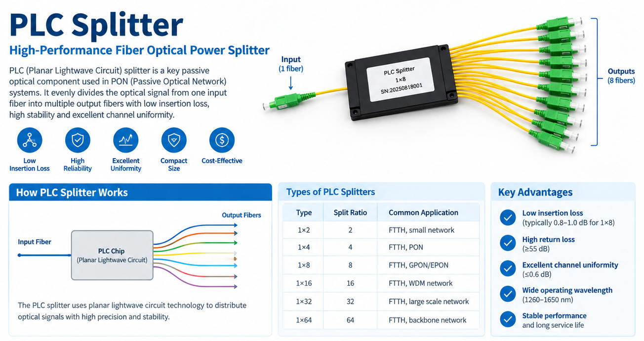
A PLC splitter, short for Planar Lightwave Circuit splitter, is a passive fiber optic component that divides an optical signal from one input fiber into multiple output fibers.
For example:
- 1×2 PLC splitter divides one input into two outputs.
- 1×4 PLC splitter divides one input into four outputs.
- 1×8 PLC splitter divides one input into eight outputs.
- 1×16 PLC splitter divides one input into sixteen outputs.
- 1×32 PLC splitter divides one input into thirty-two outputs.
- 1×64 PLC splitter divides one input into sixty-four outputs.
Higher splitting ratios are also available for specific PON network architectures.
The splitting process is passive, meaning the device does not amplify, regenerate, or electronically process the optical signal. Instead, it divides the available optical power among multiple output ports.
Simple PLC Splitter Structure
A typical PLC splitter consists of several key components:
- Input fiber
- Optical splitter chip
- Planar waveguide circuit
- Output fibers
- Protective package
- Fiber connectors or splice pigtails
The optical splitter chip is the core component. It uses planar waveguide technology to distribute the input optical signal to multiple outputs.
How Does a PLC Splitter Work?
A PLC splitter uses planar waveguide technology to divide an optical signal.
The basic process can be described as:
Optical Input → PLC Optical Circuit → Optical Power Distribution → Multiple Outputs
When an optical signal enters the splitter, the optical waveguide structure distributes the signal across multiple output channels.
For a theoretically ideal 1×8 splitter, the input optical power would be distributed approximately equally among eight output ports.
However, real optical networks have additional losses caused by:
- Splitting loss
- Insertion loss
- Connector loss
- Fiber loss
- Packaging loss
- Wavelength-related characteristics
Therefore, a 1×8 PLC splitter does not simply provide one-eighth of the original optical power without loss. Network engineers must consider the total optical budget when designing a PON network.
What Are the Main Types of PLC Splitters?
PLC splitters can be classified according to splitting ratio, packaging method, connector configuration, and application environment.
1×N PLC Splitter
A 1×N PLC splitter has one optical input and multiple optical outputs.
Common configurations include:
- 1×2
- 1×4
- 1×8
- 1×16
- 1×32
- 1×64
1×N splitters are widely used in FTTH and PON distribution networks.
2×N PLC Splitter
A 2×N PLC splitter has two input fibers and multiple outputs.
Common configurations include:
- 2×2
- 2×4
- 2×8
- 2×16
- 2×32
- 2×64
These configurations can be used in network architectures that require dual input paths or more specialized optical distribution designs.
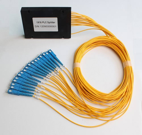
PLC Splitter Packaging Types
The internal PLC technology can be packaged in several ways depending on the installation environment.
Bare Fiber PLC Splitter
A bare PLC splitter has minimal packaging and is normally supplied with exposed optical fibers.
Features
- Very compact
- Lightweight
- Easy to integrate
- Suitable for splice trays and optical modules
- Cost-effective
Bare PLC splitters are commonly installed inside fiber optic distribution boxes, splice closures, and other optical equipment.
Blockless PLC Splitter
A blockless PLC splitter uses a compact protective tube or housing around the splitter assembly.
Advantages
- Compact construction
- Flexible installation
- Easy fiber routing
- Suitable for dense optical distribution systems
Blockless PLC splitters are frequently used in FTTH distribution equipment.
Cassette PLC Splitter
A cassette PLC splitter is integrated into a protective cassette housing.
Advantages
- Easy installation
- Organized fiber management
- Better mechanical protection
- Suitable for rack-mounted or modular systems
Cassette splitters are useful when installers need to quickly deploy or replace optical splitting modules.
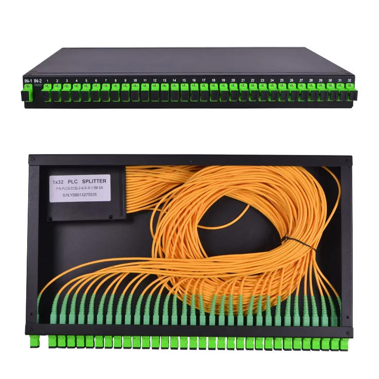
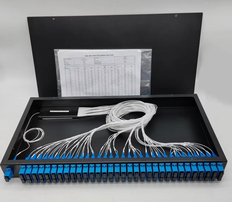
Rack-Mount PLC Splitter
Rack-mounted PLC splitters are installed inside standard optical distribution racks.
They are commonly used in:
- Telecom central offices
- Data centers
- Network rooms
- Large FTTx systems
- PON distribution equipment
Their standardized housing makes installation and maintenance easier in centralized network environments.
What Are the Advantages of PLC Splitters?
PLC splitters provide several advantages over traditional optical splitting technologies.
1. Uniform Splitting
One of the major advantages of PLC technology is relatively uniform optical power distribution among output ports.
This is particularly important for PON networks where multiple subscribers need stable optical signal levels.
A high-quality PLC splitter can provide good port-to-port uniformity across its operating wavelength range.
2. Low Insertion Loss
PLC splitters are designed to provide relatively low insertion loss for their specified splitting ratio.
Lower optical loss is important because PON networks have limited optical power budgets.
For example, as the splitting ratio increases from 1×8 to 1×32 or 1×64, the theoretical splitting loss increases.
Therefore, the splitter ratio must be selected according to the available optical budget.
3. Wide Operating Wavelength Range
PLC splitters are commonly designed to operate across multiple telecommunications wavelengths.
Depending on the specific product, they may support wavelength ranges covering common PON transmission windows such as:
- 1310 nm
- 1490 nm
- 1550 nm
Some products are designed for broader wavelength applications.
The exact operating range should always be checked against the manufacturer’s specification.
4. High Reliability
PLC splitters are passive optical components and do not require electrical power.
There are no active electronic components inside the optical splitting path, which helps simplify network architecture.
With proper packaging and environmental protection, PLC splitters can be deployed in demanding telecom environments.
5. Compact Size
PLC technology allows many optical channels to be integrated into a relatively small package.
This is especially useful for:
- FTTH distribution boxes
- Fiber termination boxes
- Optical network terminals
- Splice closures
- Rack-mounted optical distribution systems
Compact packaging helps installers manage high-density fiber networks more efficiently.
6. High Splitting Ratios
PLC technology can support high splitting ratios while maintaining relatively consistent output performance.
Common products include:
1×2 → 1×4 → 1×8 → 1×16 → 1×32 → 1×64
This makes PLC splitters suitable for different network scales.
PLC Splitter Applications
PLC splitters are mainly used in passive optical networks and fiber optic access networks.
1. FTTH Networks
FTTH is one of the most important applications of PLC splitters.
A typical FTTH network may include:
OLT → Feeder Fiber → PLC Splitter → Distribution Fiber → Subscriber → ONT/ONU
The splitter allows one optical line from the network side to serve multiple users.
For example, a 1×32 PLC splitter can distribute one optical input toward 32 output branches.
2. GPON Networks
GPON networks use passive optical distribution to connect an OLT with multiple ONUs/ONTs.
PLC splitters can be installed at different points in the optical distribution network depending on the network architecture.
They help operators share fiber infrastructure among multiple subscribers.
3. EPON Networks
PLC splitters are also commonly used in EPON networks.
The basic principle is similar:
OLT → Fiber Distribution Network → PLC Splitter → Multiple ONUs
The splitter itself does not determine whether the network uses GPON or EPON. Instead, it functions as a passive optical distribution component.
4. FTTB and FTTC Networks
PLC splitters can also be used in other FTTx architectures.
For example:
- Fiber to the Building (FTTB)
- Fiber to the Curb (FTTC)
- Fiber to the Premises (FTTP)
The appropriate splitter ratio and installation location depend on network topology and optical budget.
5. Telecom Networks
Telecommunication operators use PLC splitters for optical signal distribution in access networks.
They may be installed in:
- Central offices
- Fiber distribution hubs
- Outdoor cabinets
- Distribution boxes
- Street cabinets
- Fiber splice closures
6. CATV and Optical Distribution
PLC splitters can also be used in optical distribution systems where optical signals need to be divided among multiple destinations.
The actual splitter specification must match the wavelength, optical power, connector type, and network architecture.
PLC Splitter vs FBT Splitter
One of the most common questions when selecting an optical splitter is:
What is the difference between PLC and FBT splitters?
FBT stands for Fused Biconical Taper. It is another passive optical splitting technology.
The two technologies differ in manufacturing method, splitting uniformity, scalability, and typical applications.
| Feature | PLC Splitter | FBT Splitter |
|---|---|---|
| Technology | Planar Lightwave Circuit | Fused Biconical Taper |
| Splitting uniformity | Generally high | Can vary with configuration |
| High splitting ratio | Suitable | Less practical for high ratios |
| Multi-output scalability | Excellent | More limited |
| Wavelength performance | Broad and consistent | More wavelength dependent |
| Compactness | High | Depends on construction |
| FTTH application | Very common | Also possible |
| Large PON networks | Well suited | Less commonly selected |
| Manufacturing method | Semiconductor/planar waveguide process | Fiber fusion/tapering |
| Typical high-density application | Excellent | More limited |
Which Technology Should Be Used?
The answer depends on the network requirements.
PLC splitters are generally suitable when the project requires:
- High splitting ratios
- Uniform output power
- Multiple output channels
- Compact packaging
- PON/FTTH deployment
FBT splitters may still be appropriate for certain low-ratio or specialized applications.
PLC Splitter vs Fiber Coupler
A fiber coupler and PLC splitter are related but should not always be treated as identical products.
A fiber coupler can be designed to combine or divide optical signals, while a PLC splitter is specifically engineered using planar waveguide technology for controlled optical power distribution.
For modern high-density PON applications, PLC splitters are commonly selected because of their scalability and uniformity.
PLC Splitter Insertion Loss
Insertion loss is one of the most important specifications when purchasing a PLC splitter.
It represents the amount of optical power lost when the optical signal passes through the splitter.
The theoretical splitting loss can be approximated using:
Splitting Loss = 10 × log₁₀(N)
where N is the number of output ports.
For example:
- 1×2: approximately 3 dB theoretical splitting loss
- 1×4: approximately 6 dB
- 1×8: approximately 9 dB
- 1×16: approximately 12 dB
- 1×32: approximately 15 dB
- 1×64: approximately 18 dB
Actual insertion loss is higher because real devices have excess loss and other optical losses.
Therefore, network designers should use the manufacturer’s maximum insertion-loss specification rather than relying only on theoretical values.
How to Choose the Right PLC Splitter?
Selecting a PLC splitter should be based on several technical and installation factors.
1. Choose the Correct Splitting Ratio
The most common ratios are:
- 1×2
- 1×4
- 1×8
- 1×16
- 1×32
- 1×64
A higher ratio allows more users to share one input fiber, but it also produces greater optical splitting loss.
2. Check the Optical Budget
This is critical for PON network design.
The total optical loss may include:
Fiber Loss + Connector Loss + Splice Loss + Splitter Loss + Other System Losses
The selected PLC splitter must operate within the available optical power budget.
3. Select the Correct Wavelength
Make sure the splitter supports the wavelengths used by the network.
Typical PON-related wavelengths may include:
- 1310 nm
- 1490 nm
- 1550 nm
For specialized systems, other wavelength specifications may be required.
4. Choose the Right Connector
Common connector configurations include:
- SC/UPC
- SC/APC
- LC/UPC
- LC/APC
SC/APC is widely used in many FTTH environments because angled polishing can provide low back reflection.
However, the connector should always match the rest of the network.
5. Consider the Installation Environment
For indoor applications, compact bare, blockless, cassette, or rack-mounted products may be suitable.
For outdoor installations, additional environmental protection may be required.
Important factors include:
- Operating temperature
- Humidity
- Mechanical protection
- Waterproofing
- UV exposure
- Installation method
PLC Splitter Specifications Buyers Should Check
When purchasing PLC splitters, buyers should pay attention to the following specifications:
| Specification | Why It Matters |
|---|---|
| Splitting Ratio | Determines the number of output branches |
| Insertion Loss | Determines optical power loss |
| Return Loss | Indicates reflected optical power |
| Operating Wavelength | Must match network wavelengths |
| Operating Temperature | Determines environmental suitability |
| Fiber Type | Must match the network fiber |
| Connector Type | Determines installation compatibility |
| Package Type | Determines installation method |
| Directivity | Important for optical isolation |
| Uniformity | Indicates output power consistency |
| PDL | Important for polarization-sensitive applications |
| Dimensions | Important for high-density installations |
PLC Splitter for FTTH: Typical Network Structure
A typical FTTH deployment may look like:
OLT → Feeder Fiber → Fiber Distribution Hub → PLC Splitter → Distribution Fiber → Drop Cable → ONT/ONU
The PLC splitter acts as the passive distribution point between the feeder and multiple subscriber lines.
Depending on the network architecture, operators may use centralized splitting or distributed splitting.
Centralized vs Distributed PLC Splitting
Centralized Splitting
In a centralized architecture, the PLC splitter is installed at a central distribution location.
Advantages
- Easier centralized management
- Simplified maintenance
- Convenient splitter access
- Suitable for certain network architectures
Considerations
Longer distribution fibers may be required, and the network must be carefully designed around the optical budget.
Distributed Splitting
Distributed splitting places splitters at different points within the access network.
For example:
1×4 + 1×8 = 1×32
This approach can reduce the amount of fiber required in some network designs and provide greater flexibility in subscriber distribution.
However, network engineers need to carefully calculate cumulative optical loss.
PLC Splitter Manufacturing and Quality Control
The quality of a PLC splitter depends on both the optical chip and the manufacturing process.
Important quality-control stages may include:
- Optical chip inspection
- Fiber alignment
- Waveguide coupling
- Packaging
- Fiber assembly
- Connector termination
- Insertion-loss testing
- Return-loss testing
- Environmental testing
- Final inspection
For fiber optic distributors and telecom contractors, consistent optical performance between batches is particularly important.
Why Buy PLC Splitters from a Professional Fiber Optic Manufacturer?
For large FTTH or PON projects, supplier selection is not only about unit price.
Buyers should also evaluate:
Product Consistency
Different batches should maintain consistent optical specifications.
Customization
Professional manufacturers may provide customized:
- Splitting ratios
- Connector types
- Fiber lengths
- Package styles
- Labels
- Packaging
- Cable configurations
Quality Testing
Optical testing helps verify insertion loss, return loss, uniformity, and other parameters.
Production Capacity
For large projects, production capacity and delivery reliability can be as important as the product specification.
Technical Support
A supplier with technical knowledge can help customers select suitable splitter configurations based on network requirements.
Common PLC Splitter Problems
High Insertion Loss
Possible causes include:
- Poor-quality splitter
- Connector contamination
- Damaged fiber
- Poor splicing
- Incorrect installation
The entire optical path should be tested rather than assuming the splitter is always the cause.
Uneven Output Power
If output power varies significantly between ports, installers should check:
- Splitter specifications
- Connector condition
- Fiber bending
- Splice quality
- Optical test equipment
A properly specified PLC splitter should provide controlled output uniformity within its stated limits.
Optical Signal Too Weak
A high splitting ratio can significantly increase optical loss.
For example, replacing a 1×8 splitter with a 1×32 splitter adds theoretical splitting loss.
Therefore, increasing the number of users per input should always be evaluated against the available optical budget.
PLC Splitter FAQ
What does PLC stand for in fiber optics?
PLC stands for Planar Lightwave Circuit. A PLC splitter uses planar optical waveguide technology to divide one optical signal into multiple output signals.
What is a 1×8 PLC splitter?
A 1×8 PLC splitter has one optical input and eight optical outputs. It distributes one incoming optical signal among eight output branches.
What is a 1×32 PLC splitter?
A 1×32 PLC splitter divides one optical input into 32 output channels. It is commonly used in FTTH and PON distribution networks.
Is a PLC splitter passive?
Yes. A PLC splitter is a passive optical device and does not require electrical power to divide optical signals.
What is the difference between PLC and FBT splitters?
PLC splitters use planar waveguide technology and are well suited to high splitting ratios and uniform optical distribution. FBT splitters use fused biconical taper technology and are often used for lower splitting ratios or specific optical applications.
Can PLC splitters be used for GPON?
Yes. PLC splitters are widely used as passive optical distribution components in GPON networks, provided the splitter specifications meet the network’s optical budget and wavelength requirements.
Can PLC splitters be used for EPON?
Yes. PLC splitters can also be used in EPON networks because they are passive optical distribution devices.
Which is better: 1×16 or 1×32 PLC splitter?
Neither is universally better. A 1×32 splitter supports more output branches but introduces greater splitting loss than a 1×16 splitter. The correct choice depends on the number of subscribers and available optical power budget.
What connectors are available for PLC splitters?
Common connector options include SC, LC, UPC, and APC configurations. The correct connector should match the network equipment and installation requirements.
How long does a PLC splitter last?
A properly manufactured and correctly installed PLC splitter can provide long-term service in a suitable operating environment. Actual service life depends on product quality, packaging, temperature, humidity, mechanical stress, and installation conditions.
Conclusion
A PLC splitter is a key passive component for modern fiber optic access networks. Using Planar Lightwave Circuit technology, it divides one optical input into multiple outputs while providing good splitting uniformity, compact packaging, and scalable splitting ratios.
PLC splitters are widely used in FTTH, GPON, EPON, FTTx, telecom, and optical distribution networks.
When selecting a PLC splitter, buyers should consider more than the splitting ratio. Important factors include insertion loss, optical budget, operating wavelength, connector type, package design, uniformity, operating environment, and installation method.
For high-density PON and FTTH deployments, common configurations such as 1×8, 1×16, 1×32, and 1×64 PLC splitters provide flexible solutions for distributing optical signals to multiple users.
For a reliable network, the splitter should be selected according to the complete optical link budget rather than simply choosing the highest available splitting ratio.
If you are looking for PLC splitters for FTTH, GPON, EPON, or other fiber optic applications, provide the required splitting ratio, connector type, fiber length, package type, and quantity. OUFU professional fiber optic manufacturer can then recommend a suitable configuration and specification.