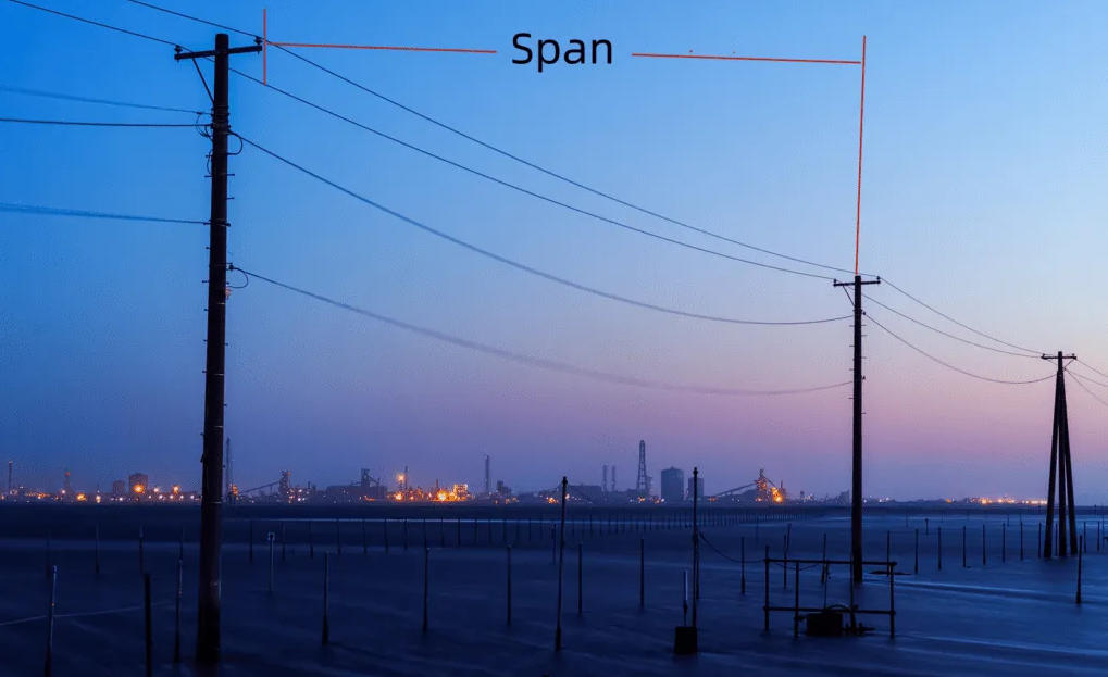
Selecting the correct span length and fiber core count for ADSS (All-Dielectric Self-Supporting) fiber optic cables is the core of overhead power communication project design. Unlike ordinary aerial fiber cables, ADSS cables bear all mechanical tension, wind load, ice load, and long-term electrical field erosion in overhead environments. Improper selection of span and core count will lead to excessive cable sag, fiber breakage, sheath aging, communication failure, or unnecessary project cost waste. To achieve stable operation, reasonable cost, and long-term expandability, ADSS cable selection must be comprehensively judged from multiple dimensions including cable structure, material configuration, power grid voltage level, application scenario, meteorological environment, and long-term operation requirements. This article provides a full-dimensional selection standard for ADSS span and core count suitable for global power transmission and distribution projects.
1. ADSS Cable Structural Dimension: The Foundation of Span Capacity
The internal structure of ADSS cable directly determines its tensile strength, sag performance, and maximum allowable span. Different structural designs correspond to completely applicable span ranges, which is the primary basis for engineering selection. ADSS cables are mainly divided into two structural types: central tube structure and layer stranded structure, with huge differences in mechanical performance and application scenarios.
Central Tube ADSS Cable features a simple single-tube integrated structure, with all optical fibers placed in a loose tube filled with fiber paste, and no multi-layer stranded reinforcement structure. Its advantages are light weight, small outer diameter, low cost, and good bending performance. However, the tensile strength is limited, and the structural stability under heavy load is poor. Structurally, this type of ADSS cable is only suitable for short-span overhead scenarios. The standard applicable span is 30m to 100m, which is mostly used for urban and rural low-voltage distribution network overhead lines. It cannot be used for medium and long-span scenarios such as river crossing and mountain crossing, because it is prone to excessive sag and fiber stress deformation under long-distance tension.
Layer Stranded ADSS Cable adopts multi-layer stranded loose tube structure, with optical units stranded in layers around the central framework, equipped with high-strength dielectric reinforcing strands. This structural design greatly improves the overall tensile strength, pressure resistance and structural stability of the cable. The layered structure can evenly disperse wind load, ice load and long-term tension, avoiding local stress concentration. Its applicable span covers 100m to 1500m, covering medium, long and ultra-long span engineering scenarios. All high-voltage long-distance trunk lines and complex terrain crossing projects must adopt layer-stranded ADSS cables. In addition, the layer stranded structure can accommodate more fiber cores, which is the only structural option for medium and large core count (48 cores and above) ADSS cables.
2. Material Dimension: Sheath & Reinforcement Material Decides Span Safety Margin
The sheath material and non-metallic reinforcement material of ADSS cable are key factors affecting its anti-aging, anti-electric corrosion and wind/ice resistance, which indirectly determine the safe design span of the project. Even for the same structural type of ADSS cable, different material configurations will lead to completely different span selection standards.
In terms of outer sheath materials, there are two mainstream types: PE sheath and AT anti-tracking sheath. PE (Polyethylene) sheath has the advantages of low cost and good flexibility, but poor resistance to high-voltage electric trace erosion. It is only suitable for zero electric field or weak electric field environments of low-voltage power lines. The matching span of PE sheath ADSS is relatively conservative. Under the same tower distance, the design span needs to be reduced by 10% compared with AT sheath cables to avoid sheath cracking and aging caused by electric field interference. AT (Anti-Tracking) special anti-electric erosion sheath is modified with special polymer materials, which can resist corona discharge, electric trace and chemical erosion in strong electric field environments. It has excellent environmental adaptability, stable mechanical performance in long-term high-voltage operation, and allows a larger safe span margin. All ADSS cables used in 110kV and above high-voltage projects must use AT sheath, and the span can be designed according to the standard maximum tensile value of the cable.
In terms of reinforcement materials, high-strength aramid yarn and dielectric glass fiber strands are the mainstream configurations. High-quality high-tensile aramid yarn has ultra-high tensile strength and low elongation, which can effectively control cable sag under long-span tension and prevent fiber strain. Low-grade reinforcement materials have large thermal expansion coefficient and easy deformation, which will cause excessive sag in high-temperature environments and ice-covered sag in low-temperature environments. For ultra-long span projects above 400m, high-density enhanced aramid yarn reinforced ADSS cable must be selected to ensure that the EDS (Everyday Stress) and MAT (Maximum Allowable Tension) of the cable meet IEC 60794 standard requirements.
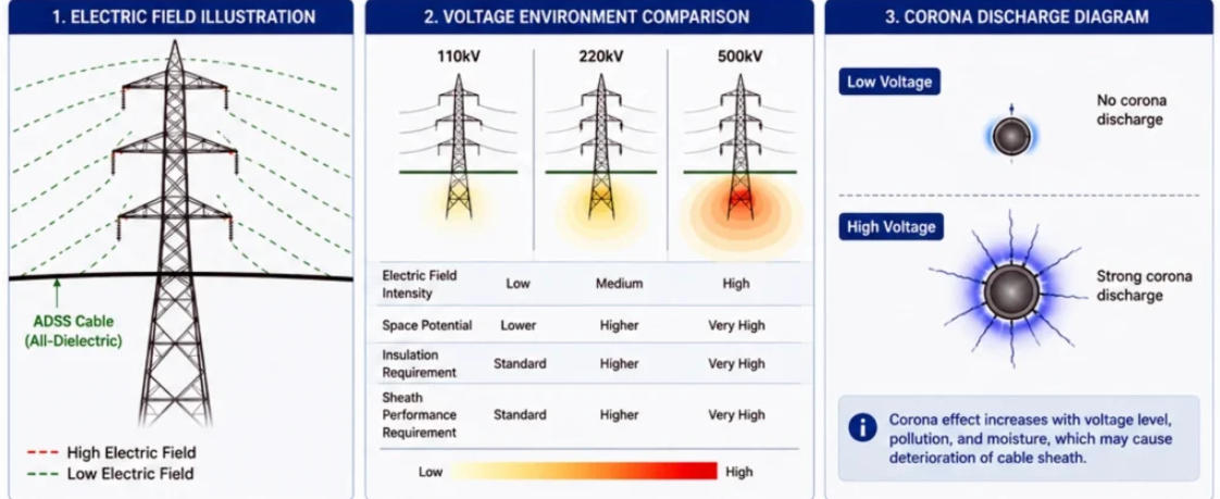
3. Voltage Level Dimension: Electric Field Environment Restricts Span and Model Selection
The voltage grade of the matched power line is a decisive factor for ADSS cable span and material selection, and is also a key dimension that distinguishes professional engineering selection from ordinary selection. Different voltage levels form different electric field intensities, which put forward different requirements for cable span and sheath materials.
For 10kV/33kV low and medium voltage distribution networks, the on-site electric field is weak, and there is no electric trace erosion risk. PE sheath central tube or ordinary layer-stranded ADSS cables can be selected. The conventional design span ranges from 30m to 150m, and the core count is mainly 6 cores, 12 cores and 24 cores, which meets the daily communication, remote monitoring and fault signal transmission of urban and rural distribution networks.
For 110kV high-voltage transmission lines, the strong alternating electric field will cause corona discharge on the surface of ordinary cables. At this time, AT anti-tracking sheath is mandatory, and the span design needs to comprehensively consider tower bearing capacity and electric field distribution. The conventional safe span is 150m to 400m, and 24-core to 72-core layer-stranded ADSS cables are mostly used to meet the communication scheduling and protection channel needs of main substations.
For 220kV and above ultra-high voltage trunk lines, the electric field environment is complex and the line tower spacing is large. It is necessary to use double-layer AT sheath reinforced long-span ADSS cables. The design span can reach 400m to 800m, and the core count is mainly 96 cores and 144 cores, which is used for cross-regional power grid scheduling, data transmission and operator resource leasing.
4. Application Scenario & Meteorological Environment Dimension: Optimize Span Design Margin
Different terrain and meteorological environments will bring additional loads such as wind pressure, ice coating and temperature difference to ADSS cables, which must be fully considered in span selection to avoid operation risks. Scenario-based fine selection is the key to improve the service life of ADSS cables.
In flat urban and suburban conventional scenarios, the wind and ice load is small, the terrain is flat, and the tower foundation is stable. The span can be designed according to the standard rated span of the cable, with no need for excessive reduction. The core count is selected according to the current demand plus 20% spare fibers, which is the most economical and applicable scheme for conventional power distribution projects.
In coastal strong wind and salt fog scenarios, perennial strong wind, typhoon weather and salt fog corrosion will accelerate cable aging and increase wind-induced galloping tension. The design span must be reduced by 10%–15% on the basis of the standard span to reduce cable tension and wind vibration amplitude. At the same time, salt-fog-resistant modified sheath materials are matched to ensure long-term stable operation.
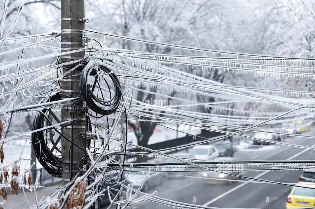
In high-latitude heavy ice and snow scenarios, the ice coating on the cable will greatly increase the self-weight load, which is the main cause of cable breakage and tower collapse in winter. The span needs to be reduced by 20%–30% in a targeted manner, and high-tensile reinforced ADSS cables with stronger load-bearing capacity are selected to resist ice and snow load impact.
In mountainous area, river crossing and valley crossing scenarios, the tower spacing is large and the terrain is complex, which belongs to ultra-long span working conditions. It is necessary to customize long-span ADSS cables, and strictly calculate sag tension and wind ice load parameters to ensure that the cable does not touch the ground, cross obstacles or exceed the tension limit.
5. Core Count Selection Multi-Dimensional Standard: Demand, Expansion and Commercial Value
ADSS fiber core count selection cannot only rely on current usage demand, but also comprehensively consider service scenarios, network expansion plans, project nature and commercial value, to avoid repeated investment and resource waste.
Small core count (6–12 cores) is suitable for single township power distribution, single substation peripheral supporting lines, and small photovoltaic and wind power station auxiliary communication. The demand is only for basic SCADA remote control, fault alarm and simple data transmission, with low data volume and no subsequent large-scale expansion demand. This core count is matched with short-span central tube ADSS cables, with low overall project cost and high cost performance.
Medium core count (24–48 cores) is the most versatile mainstream specification, suitable for county-level power grid reconstruction, urban distribution network trunk lines, and conventional 110kV power lines. It can meet the needs of power scheduling, video monitoring, smart meter data transmission, and reserve enough spare cores for subsequent network upgrading and equipment access, which is the preferred scheme for most medium and small power EPC projects.
Large core count (72–144 cores) is oriented to national and provincial main grid trunk lines, cross-region transmission projects, and large-scale new energy base supporting lines. On the one hand, it meets the multi-channel communication needs of power dispatching, protection, administration and monitoring; on the other hand, the redundant fiber cores can be leased to telecom operators for 5G backhaul and FTTH network construction, creating additional long-term economic benefits for power grid projects.
6. Matching Rule of Span and Core Count (Key Engineering Experience)
There is a strict matching relationship between ADSS cable span and core count. Blind matching will lead to performance mismatch or cost waste. Short-span scenarios are not suitable for large-core thick cables, which will cause excessive self-weight and increased sag; long-span scenarios cannot use small-core thin cables, which have insufficient tensile strength and hidden safety hazards.
6–12 core central tube ADSS is limited to short spans below 100m; 24–48 core layer-stranded ADSS is compatible with 80–350m medium spans, covering most conventional power projects; 72–144 core large-core reinforced ADSS, with thick structure and high tensile strength, is suitable for 100–1500m medium and ultra-long spans, and is exclusively used for high-voltage main lines and complex terrain projects.
Conclusion
The scientific selection of ADSS cable span and core count requires comprehensive verification from structural form, material performance, voltage level, meteorological terrain, and project long-term demand. Taking structural materials as the mechanical foundation, voltage electric field as the limiting condition, and scenario demand as the design goal, while reserving sufficient safety margin and fiber redundancy, can ensure that the ADSS optical cable system operates stably for more than 20 years, and maximize the economic and engineering value of power communication projects.
ADSS Cable FAQ
Q1: What determines the maximum span of ADSS aerial fiber cable?
A: Four key factors decide ADSS maximum allowable span: internal cable structure (central tube / layer stranded), outer sheath material (PE vs AT), reinforcement aramid material, local weather (ice load, wind speed) and overhead power line voltage grade. Layer stranded + AT sheath + high-density aramid supports much longer span than central tube PE type. Central tube ADSS is commonly limited within 100m span, while reinforced layer stranded ADSS can reach up to 800m for river/mountain crossing.
Q2: What is the span difference between PE sheath ADSS and AT anti-tracking ADSS?
A: PE jacket ADSS only applies for 10kV/33kV low-voltage distribution lines with weak electric field; its designed span needs to shrink 10% under same tower distance due to poor anti-electric corrosion. AT anti-tracking sheath resists corona leakage and electrical tracking under strong high voltage field (≥110kV), keeping full rated design span without extra span reduction. All overhead lines above 110kV HV grid must adopt AT sheath ADSS.
Q3: Central tube vs layer stranded ADSS, which one for long span project?
A: Layer stranded ADSS is the only option for medium & long span over 150m. Central tube ADSS features lightweight and low cost but limited tensile strength, suitable for short span 30–100m urban pole distribution. Layer stranded arranges loose fiber units around FRP central strength member with stranded aramid reinforcement, uniform stress dispersion against wind & ice load, available from 80m up to 800m ultra-long span. Besides, layer stranded structure can manufacture high core count from 48C to 144C easily.
Q4: How many spare fiber cores should we reserve when choosing ADSS core count?
A: Industry standard rule: reserve minimum 20% spare fibers for future grid upgrade, smart meter access, video monitoring and telecom fiber leasing. For example, if project needs 20 working fibers for SCADA & relay protection, select 24-core ADSS instead of 12-core. Large trunk HV lines (220kV+) prefer extra surplus cores to rent to local ISP for 5G backhaul and FTTH construction for extra revenue.
Q5: Recommended core count matching different voltage power grid?
A:
- 10kV/33kV distribution network: 6/12/24 core ADSS for township distribution, small substation communication;
- 110kV conventional transmission line: 24C~72C layer stranded AT ADSS for county & municipal main power channel;
- 220kV & above EHV backbone line: 96C/144C high-core ADSS for cross-region power dispatching and operator fiber lease.
Q6: Do heavy ice/snow or coastal typhoon areas need to shorten ADSS designed span?
A: Yes. Heavy icing cold area (Canada, North Europe, high-altitude mountain): reduce original rated span by 20%~30% to offset extra ice weight load. Tropical coastal salt fog & frequent typhoon zone: cut design span 10%~15% to avoid cable galloping, excessive sag and sheath fatigue damage. Custom anti-ice modified ADSS is available for extreme cold environment upon OEM.
Q7: Can large core 96/144 core ADSS be used for short span below 50m pole line?
A: Not recommended economically. High-core layer stranded ADSS owns thicker cable diameter and heavier self-weight, wasting extra material cost on short-distance overhead. Short span under 50m prefers cost-effective 6C/12C central tube PE ADSS to control overall project investment.
Q8: What ADSS specification for wind farm / solar power station communication?
A: Most new energy plants choose 24~72 core AT sheath layer stranded ADSS with medium span 80–300m. These fibers serve fan real-time monitoring, transformer station data transmission and power dispatching signal, with spare cores reserved for later new equipment expansion.
Q9: What is EDS and MAT related to ADSS span design?
A: EDS = Everyday Stress, long-term working tension under normal temperature & basic weather; MAT = Maximum Allowable Tension under extreme ice/wind condition per IEC60794. Engineers calculate EDS & MAT data to confirm safe span, ensuring actual installation tension never exceeds factory certified MAT value.
Q10: ADSS or OPGW, which one to pick for overhead power communication span design?
A: OPGW is embedded inside ground wire of transmission tower, used for new-built high voltage tower construction only. ADSS is self-supporting, mounted separately on tower cross arm, perfect for old grid renovation, distribution network upgrade and long-distance crossing project with flexible span design from 30m to 800m, lower construction cost than OPGW for retrofit project.